
Minimum output was 0.55V, max 4.8V so I soldered up an old phono lead to make a resistor divider of 10:1 (power amp is the usual 1V for max output).
XSCOPE OSCILLOSCOPE SOFTWARE GENERATOR
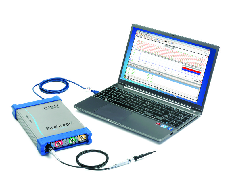
I bought a XR2206 signal generator kit, and assembled it. I bought a toy scope, and used it to fix my amp. I would be grateful for any help or advice. The only fly in the ointment seems to be that my amplifier (at 100 W/ch) has 59v power rails, and the DSO150 has an input max of 50v.Ĭould I use a 10:1 resistor divider to bring me in range? And if so what value should the divider be? I'm afraid the whole input/output impedance thing is a close book to me. The online reviews seem quite favourable (although they all point out it's not a real 'scope, which raises the question of what's "real"). JYE Tech: DIY Oscilloscopes, DIY Kits for HobbyistsĪppears to be the cheapest cased scope that does the sort of thing I need. I could buy a s/h "real" scope but they're pretty big and, still fetch actual money (especially shipping!!). I only need audio frequencies (50 Mhz would be of surpassing irrelevance), and absolute accuracy doesn't matter much either. But I don't appear to need a very fancy one. To this end I think I need an oscilloscope. My plan is to compare the left board with the right board until I find a difference, and then check components. As long as I drive a symmetrical stereo test signal in, I have an ideal source of reference voltages and signals. It literally has two identical boards, and the left on is working perfectly. I think I can track the fault by elimination - the circuit is a very symmetric A/B design, so I can compare the waveforms on the negative/positive sides of the circuit.Įven better, the amp is dual mono in construction.

I am not an electronics hobbyist (yet.).Ī friend (who is) re-cap'd it a couple of years ago, but logistics mean I can't get the amp to him this time. I have a 20 y/old (but nice) power amplifier, which has developed a fault in the right channel.


 0 kommentar(er)
